How to Choose a Compact Counterbalance Stacker with a Hook Attachment
2026-08-10
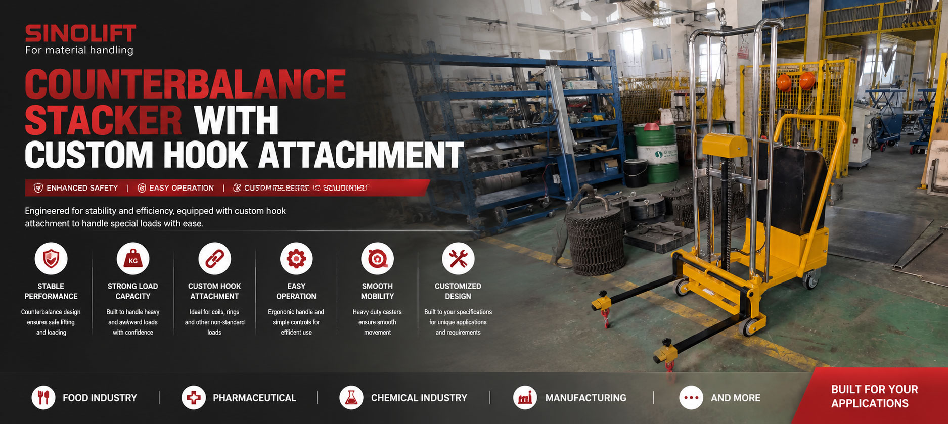
When a pallet stacker is not the right starting point
Many small lifting tasks are not pallet tasks. A component may need to be picked from an eye, a fixture may need to be lifted from a defined point, or a machine-side part may need to be positioned without using a full-size forklift. In these situations, the attachment determines whether the equipment is useful.
The supplied shipment materials show a yellow EZ counterbalance stacker with a customized front hook/support arrangement. The accompanying drawing identifies the base configuration as EZ2518F and lists a 100 kg rated load, 1,420 mm lift height, 500 mm load center, 600 mm fork length and adjustable front spacing from 30 to 600 mm.
This guide explains how a buyer should evaluate such a machine. The focus is not on claiming a particular customer result. It is on matching the machine to the load interface, route, working height and operating method.
First question: what exactly is being lifted?
Start with the load and its connection point. Provide the maximum weight, center of gravity, eye or fixture dimensions, contact surface, length and any flexible component such as a sling or cable. If the load varies, list the smallest and largest approved cases.
The 100 kg value from the supplied drawing is a useful starting limit, but it is not the only selection condition. A load can fall outside the safe working envelope if its center extends beyond the 500 mm reference, if the hook creates a long forward offset, or if the load swings during movement.
The buyer should also state whether the equipment supports the load from below, from an eye, through a shaft, or with a removable hook. That determines the correct attachment design and the inspection points needed before each use.
Second question: why use a counterbalance layout?
A counterbalance layout keeps the front load interface ahead of the mast without relying on wide front legs around the load. This can make it easier to approach a fixture, frame, machine or component from the required direction. It can also reduce interference where the front of the load needs to enter a work area.
The trade-off is that the attachment and load can extend the working envelope. A counterbalance machine still needs a clear route, stable flooring and a confirmed center of gravity. The buyer should compare the complete machine-plus-load envelope with a standard straddle stacker, pallet stacker, forklift or overhead lifting method.
Third question: what must the hook do?
A hook is not defined by its appearance. Confirm the throat opening, contact radius, latch or retention method, working load, vertical position and approach angle. If a sling, eye or lifting bar is used, its dimensions and rating must be included.
Also define the movement: transport only, lift and place, rotate, load into a machine, or position at a workbench. A hook suitable for vertical lifting may not be suitable for side pulling or turning. The approved procedure should state what is prohibited as clearly as what is allowed.
The photos show a custom front structure with hook-like end elements. They provide useful visual evidence for discussing the build, but they do not prove the attachment rating, retention method or permissible side load.
Fourth question: is the lift height enough?
The EZ2518F drawing lists a 1,420 mm lift height. Compare that value with the actual pick-up and release points, not just the highest point of a rack or machine. The attachment geometry can reduce usable clearance, especially when a load must pass over a fixture or align with a production station.
Measure the height of the load connection point, the highest obstruction, the required release level and the operator's sightline. If the load is suspended, check how its position changes when it is raised. A nominal lift height does not guarantee a stable or visible transfer at every elevation.
Fifth question: will the machine fit the route?
Measure doors, aisles, turning areas, floor joints and the final work position. Include the hook and load in every measurement. The shipment photos show the machine in a marked factory aisle, but they do not establish the dimensions of the customer's site.
The route review should also cover pedestrian separation, parking position, battery charging, emergency access and the location where the attachment is stored when not in use. A machine that fits the travel aisle can still be impractical if the operator cannot align the hook at the destination.
Standard reference points from the drawing
The supplied EZ2518F drawing provides the following project reference points:
| Item | Reference value |
|---|---:|
| Rated load | 100 kg |
| Lift height | 1,420 mm |
| Load center | 500 mm |
| Fork length | 600 mm |
| Single-fork width | 50 mm |
| Adjustable front range | 30-600 mm |
|---|---:|
| Rated load | 100 kg |
| Lift height | 1,420 mm |
| Load center | 500 mm |
| Fork length | 600 mm |
| Single-fork width | 50 mm |
| Adjustable front range | 30-600 mm |
These values should be carried into the purchase review, but the custom hook and any added adapter must be checked as part of the final configuration. If the attachment changes the forward offset or load center, the rated condition must be reassessed.
What to test before acceptance
An effective acceptance test should use the actual or representative load and follow the customer's intended sequence:
1. Inspect the mast, counterbalance body, front support and hook.
2. Confirm attachment engagement and retention.
3. Lift the approved load to the required working height.
4. Hold, travel and lower on the intended floor.
5. Check visibility and operator position throughout the route.
6. Confirm release without side pull or uncontrolled swing.
7. Record the approved load limit and prohibited operations.
2. Confirm attachment engagement and retention.
3. Lift the approved load to the required working height.
4. Hold, travel and lower on the intended floor.
5. Check visibility and operator position throughout the route.
6. Confirm release without side pull or uncontrolled swing.
7. Record the approved load limit and prohibited operations.
The shipment video can support a visual record of the finished machine, but it does not replace a load test or site commissioning. No customer productivity, safety or delivery result is claimed in this guide.
Who should consider this solution?
This type of compact counterbalance stacker may be considered for light-duty machine-side handling, component positioning, fixture lifting, workshop assembly and special access tasks where standard forks are not the correct interface. It is not a substitute for a crane, hoist or higher-capacity forklift when the load or working envelope exceeds the documented limits.
Final selection advice
Choose the EZ2518F-based concept when the task needs a compact counterbalance chassis, controlled semi-electric lifting and a custom hook or support interface for a light load. The decision should be based on the complete load case rather than the frame alone.
The most useful inquiry package includes a load drawing, maximum weight, center of gravity, hook or fixture details, required lift height, route dimensions, working frequency and acceptance method. With those inputs, the supplier can identify which parts of the EZ2518F are standard and which parts need to be engineered for the application.
Frequently asked questions
What is the EZ2518F designed to handle in this project?
The supplied project drawing identifies a 100 kg rated load and a custom hook/support configuration. The exact load type and customer process were not provided.
Can the EZ2518F lift to 1,420 mm?
The supplied drawing lists 1,420 mm as the lift height. Confirm usable height with the final attachment and load geometry.
What does the 500 mm load center mean?
It is the reference distance listed in the drawing for the rated condition. A longer hook offset or suspended load can change the effective center and must be reviewed.
What should be included in an inquiry?
Include load weight, center of gravity, hook or fixture dimensions, required height, route measurements, operating frequency and any restrictions on swing or side pull.
Contact Sinolift for a project review
Send the load drawing, connection details, maximum weight, working height, route constraints and required operating sequence for a configuration review.
Email:market@sinolift.com
WhatsApp:+8613817178390
WhatsApp:+8613817178390
Sinolift PV/EPV Light Roll Lifter for Circular Materials
How to Select a Stainless Steel Semi-Electric Stacker for Round Loads: CTD1000SR Application Guide